HFIBERCORE®
HIGH-QUALITY FIBER THROUGHOUT YOUR NETWORK
Few consumers consider that the fiber being installed might have its source point 100 km away or even farther. Over a 100 km stretch, there can be up to 50-70 splices (joints), each of which is a potential source of error in the fiber planner’s optical system budget. The joints in customer boxes and ODF also have mechanical connections, which are equally critical. An ideal system would have neither splices nor mechanical joints.
Type:
Our HFiberCORE® cables feature superior blowing properties, high flexibility, and are available in many different types:

- Nano Fiber Unit
- MTE Monotube Cable
- Air Blown Micro Cable
- Super Construction Micro Cable
- Duct Cable
- Indoor Cable
- Shallow Water Cable
Colors, Diameter, Text:

Lower Installation Costs:
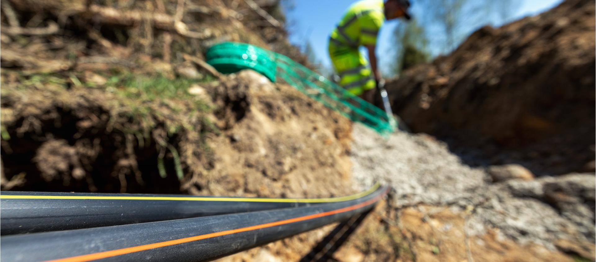
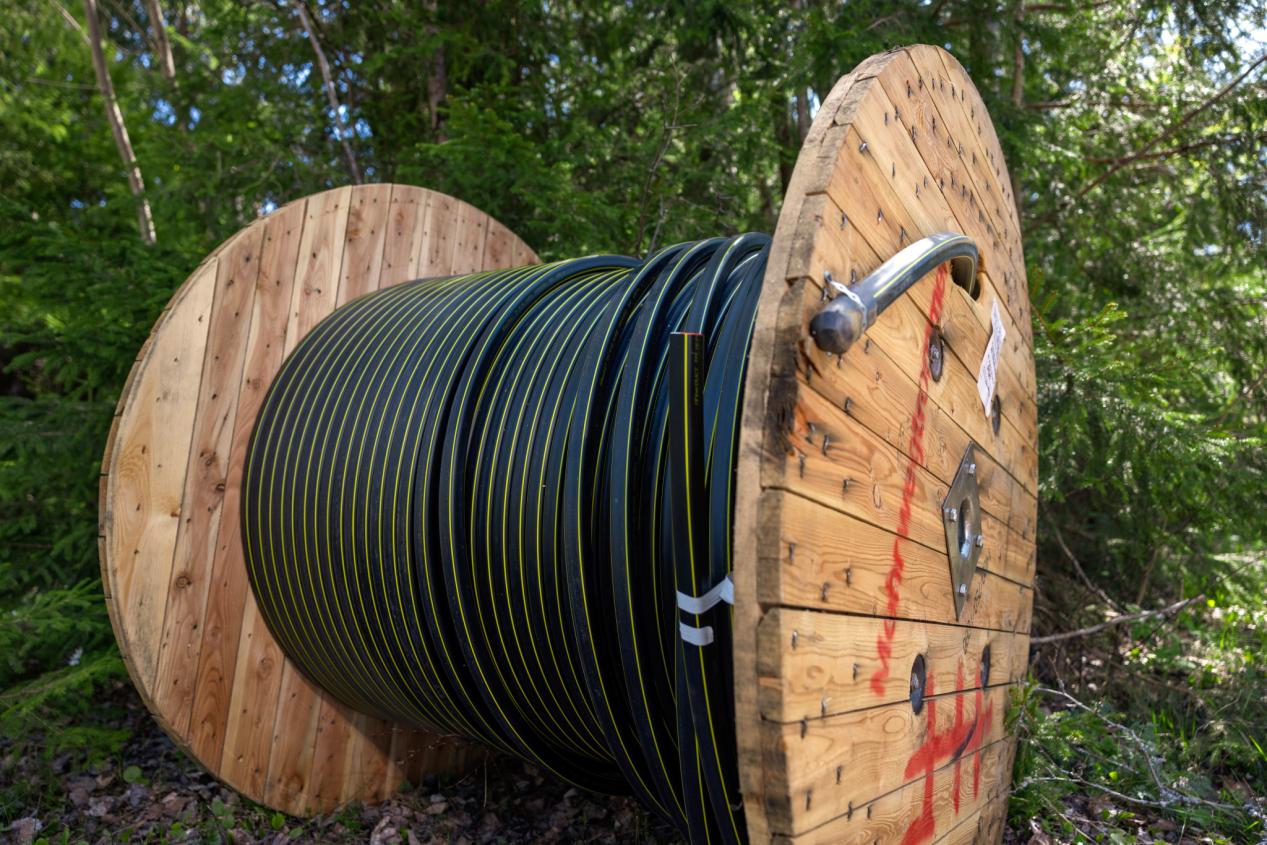
Hans Følsgaard specializes in producing customer-specific fiber cables, adjusting everything from the number of fibers to the delivery and blowing length. We might have the cables that can be blown the furthest, partly due to a surface material with a 20% lower friction coefficient (compared to competing products) and an uneven surface that allows for a 20-30% longer blowing distance.
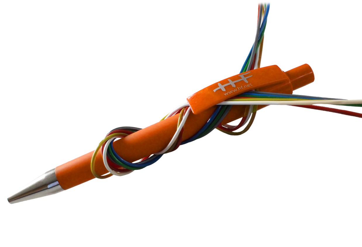
HFUltraBEND™
We may be the only supplier in the world of ultra-flexible tubes in blowing cables – HFUltraBEND™.
For years, there have been fiber optic cables on the market with super flexible tubes, including for indoor fiber optic installations, but it has not been possible to get blowing cables with these super flexible tubes until now.
Følsgaard has developed a series of blowing cables with ultra-flexible tubes – HFUltraBEND™. HFUltraBEND™ is Følsgaard’s designation for tubes that withstand bends down to a 7.5mm radius – without additional loss in the fiber due to macro-bending and without the tube breaking at the risk of damaging the fiber.
By using HFUltraBEND™ tubes, safety is ensured that the splicing installer does not have to worry about bending and twisting the tubes during the installation of fiber in closures (used under mid-span – where the center element is cut off and the tubes are pulled into and out of a mounting hole typically suited for a PG 25 fitting) or in OFD rack systems – here, the tubes no longer need to be protected by flex tubes – instead, the tubes can be led directly from where the blowing cable is mounted and fixed and led around without pathways in the rack systems. This saves space and time. Unnecessary risk of fiber damage is also avoided. Our assumption is that fiber installation will be 10-20% faster by using HFUltraBEND™ blowing cables.
Følsgaard offers to produce all types of blowing cables in HFUltraBEND™; from A12 up to A576; 4.5 mm Ø to 10.5 mm Ø.
Better Utilization of the Optical System Budget by Selecting Better Single Mode Fiber
Følsgaard can deliver blowing cables with HFUltraBEND™ with all fiber types – thereby providing a unique choice for the customer for network planning. For example, Følsgaard can deliver our HFUltraBEND™ cables with our "low loss" fiber which simultaneously provides you with about a 10% lower loss across the entire optical window compared to conventional G652D or G657A1 fibers.
This means that you get a better system budget for planning your fiber optic network. You get cables that can be blown far. Since Følsgaard has access to the world’s largest producer of single mode fiber, we can source all types of D, A1, A2, B3, B4 – 200 µm and in the future 180 µm fiber which allows us to construct the aforementioned fiber cables significantly smaller and thus guarantee further savings for you as you plan your network.
Hans Følsgaard’s blowing cables with 200 My A1- & A2-fibers are always compatible with D-fiber

All Necessary Tests Including:
IEC Test
IEC is a global organization that develops international standards covering all electrical, electronic, and related technologies. These international standards serve as the basis for national standardization.
IEC 60794 defines a series of test procedures applicable to optical fiber cables for use with telecommunications equipment and devices using similar techniques, as well as cables with a combination of both optical fibers and electrical conductors.
Typical IEC tests for fiber optic cables are as follows, and the parameters for the test method vary depending on the type of cable.
- Tensile strength: IEC 60794-1-21-E1
- Crushing: IEC 60794-1-21-E3
- Bending: IEC 60794-1-21-E11A
- Repeated bending: IEC 60794-1-21-E6
- Torsion: IEC 60794-1-21-E7
- Temperature cycling: IEC 60794-1-22-F1
- Water penetration: IEC 60794-1-22-F5B
- Connection strength: IEC 60794-1-21-E14
Type Test
A type test involves conducting a series of typical design tests to verify the new product. (This may differ from standard IEC tests.)
For example, for the new type HFiberCORE® airblown cable, we will conduct a blow test, which is not described in the IEC standards. For the new type waterflush cable, we will also perform a blow test, which is also not described in the IEC standards. Some of the new HFiberCORE® cables will undergo a simulation test in accordance with typical environmental tests during installation to ensure that our products are not only of good quality but also practical in many ways in the real world.
Blowing Test
We perform blow tests to assess the performance of cables or pipes that need to be introduced into conduits or pipelines. In the case of our fiber optic cables, such as the HFiberCORE® airblown cables you have read about, we use the blow test as a method to assess the cable's ability to be inserted or guided through pipes using compressed air or similar methods.
Our blow tests simulate the conditions the cables will face during installation, where they need to be blown through pipelines to reach their destination. The purpose is to ensure that our cables can withstand this process and remain functional without being damaged. This is a crucial validation method to ensure that our products meet the necessary requirements and expectations that may arise during actual implementation. In this way, we ensure that our solutions are not only of high quality but also robust and reliable in real installation environments.
Flush Tests
We perform flush tests to evaluate the performance of cables under the influence of water or fluid flows. This is particularly relevant for our waterflush cables, where a flush test is a method to assess the cable's resilience against water impacts.
Our flush tests simulate various conditions, such as rain, humidity, or other liquid challenges that the cables may face during installation or operation. The purpose is to ensure that our cables remain intact and functional, even when exposed to water or fluids.
This test is a crucial part of our quality control to validate whether our products meet the requirements that may arise in real environments where liquid exposure can be a factor.
Installation Tests
We conduct installation tests to ensure that our cables and telecommunications equipment perform optimally during and after installation. Our installation tests include a wide range of testing methods and scenarios designed to validate that our products function as expected in the actual installation environment.
This includes checks for proper connectivity, simulation of environmental conditions such as temperature and humidity, fault detection, performance tests, and assessment of safety requirements in the installation environment.
The purpose of our installation tests is to ensure that our products meet the necessary standards and requirements under real installation conditions. We aim to guarantee that our customers receive reliable and well-functioning solutions that meet expectations when they implement our products in their systems or environments. In this way, we ensure that our technological solutions are not only innovative but also robust and reliable in the real world.
Hans Følsgaard’s blowing cables with 200 My A1- & A2-fibers are always compatible with D-fiber
Følsgaard delivers fiber cables with a typical MFD (mode field diameter at 1310 nm) of 9.1 µm ±0.4 µm. This guarantees low splice loss and better compatibility in the fiber optic network.
Følsgaard can guarantee an MFD close to 9.1 µm, as we exclusively use single mode fiber from the world’s largest producer. By having this mode field size on all our single mode fibers, users of Følsgaard’s fiber cables avoid issues with gainers/losers during splicing and subsequent measurements.
This allows for better utilization of the system budget and simultaneously avoids unnecessary time spent on splicing and OTDR measurements.
By optimizing the fiber to an MFD of 9.1 µm ±0.4 µm, less bend sensitivity is achieved for A1- and A2-fiber than fiber with a larger MFD and at the same time, a larger normalized frequency/cut-off wavelength is obtained which ensures light that is exclusively single mode in your fiber – this provides a far better utilization of the fiber.